


When managing concrete bridge infrastructure, what you cannot see can often pose the highest risk in post-tensioned (PT) systems. In standard reinforced concrete decks, corrosion typically sounds an early alarm: rust staining, map cracking, and concrete spalling that lead to exposure of the corroded reinforcement. In PT systems, however, high-strength steel strands/wires exist inside ducts that are embedded a few inches within the concrete. Corrosive de-icing salts and moisture can migrate through microcracks, interfaces, or construction joints, triggering severe localized pitting and strand/wire section loss inside the ducts while the deck surface remains visually intact.
The decommissioning of Montreal’s historic Champlain Bridge provided an unprecedented, full-scale testbed to investigate this silent degradation. Instead of relying on small laboratory specimens, full-scale post-tensioned roadway deck slabs that had endured nearly six decades of heavy Canadian traffic and harsh freeze-thaw cycles were extracted and brought to the University of Ottawa Structures Laboratory for extensive non-destructive testing (NDT) and structural testing.
Key Takeaways for Structural Engineers & Asset Managers
- Damage-Free Surfaces Hide Severe Defects: Visual inspection alone is fundamentally unreliable for PT integrity assessment. Multiple deck zones showing no surface damage contained internal grout voids and active corrosion of the prestressing wires. To address this limitation, acoustic methods such as Impact Echo (IE) and Ultrasonic Pulse Echo (UPE) proved complementary in detecting internal defects.
- Joint Vulnerability: Wire section loss and high corrosion activity concentrated near the duct ends, specifically along construction joints and the connection interfaces where the deck slabs meet the girder top flanges. These structural interfaces served as direct pathways for moisture and chloride ingress from de-icing salts, acting as the primary entry points into the duct system. This finding was later validated through gravimetric mass loss measurements on the extracted wires.
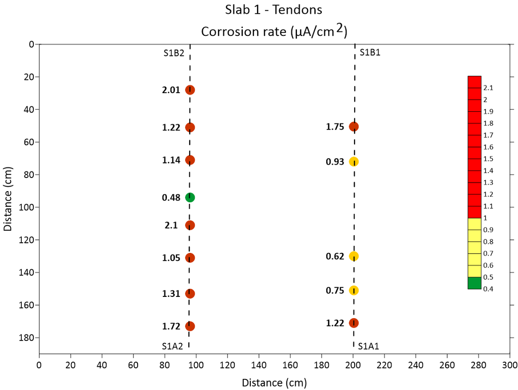
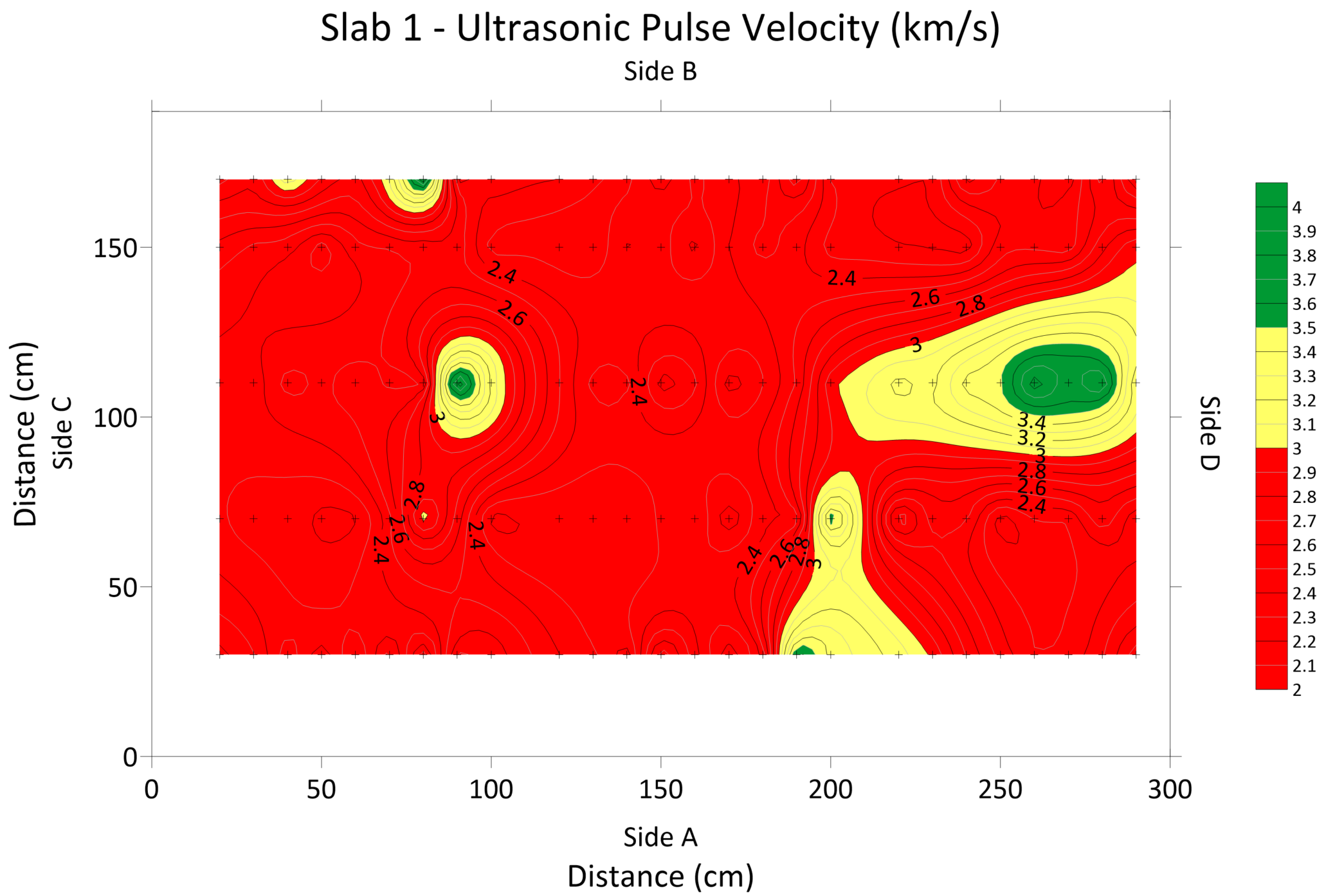
- No Single Tool for a Complete Assessment: Individual NDT methods have distinct blind spots when assessing embedded tendons. A multi-technique approach is essential for a comprehensive assessment. In this study, Ultrasonic Pulse Velocity (UPV) measurements aligned with tendon corrosion rate measurements, while UPE and IE identified defective zones with high to borderline high corrosion rates. However, NDT data alone cannot directly substitute for physical load testing to determine remaining structural capacity.
The Integrated Multi-Technique Field Assessment Protocol
Rather than treating NDT tools as isolated checks, our study evaluated how combining electromagnetic, electrochemical, and acoustic technologies creates a definitive diagnostic roadmap:
| Diagnostic Tool | Primary Target in PT Assessment | Practical Role & Limitation |
| Ultrasonic Pulse Velocity (UPV) | Internal delamination | Correlates with concrete quality ad uniformity by identifying locations of internal defects, voids or honeycombing. Influenced by surface conditions, concrete saturation degree, and aggregate type/gradation. Limited path length. |
| Half-Cell Potential | Corrosion probability in mild rebar | Identifies areas with high probability of active corrosion along tendon length. No direct assessment on extent/rate of corrosion. |
| Corrosion rate by CEPRA | Corrosion rate | Direct instantaneous corrosion rate assessment. Challenges in accurately assessing tendons within metal ducts due to potential signal interference. |
| Concrete Surface Resistivity | Concrete resistivity (related to chloride permeability) | Efficiently identifies areas susceptible to chloride penetration. Influenced by environmental conditions, saturation degree and surface conditions. |
| Ground Penetrating Radar (GPR) | Tendon location and orientation, cover depth and multi-layer systems | Quickly maps duct geometry, but cannot directly determine active corrosion rates or voids in metallic ducts. Limited function in highly reinforced areas. |
| Ultrasonic Pulse Echo (UPE) | Defects/voids within concrete | Detect voids in metallic ducts. Sensitive to size of delamination/void plane. Cannot penetrate beyond concrete-air interface. Cannot locate tendon duct with no voids. |
| Impact-Echo (IE) | Defects/voids within concrete or grout in tendon duct | Greater penetration ability than UPE. Detects objects beyond reinforcement layers. However, limited in detecting reinforcement/tendon ducts with small diameters. Cannot penetrate beyond concrete-air interface. Cannot locate tendon duct with no voids. |
Translating Data to Field Execution
The findings from the Champlain Bridge deck slabs demonstrate that no single NDT method provides an all-in-one assessment. Instead, implementing a structured, multi-technique NDT protocol bridges the gap between surface screening and internal structural integrity:
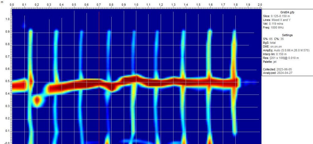
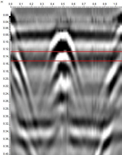
Phase 1 – GPR + Surface Electrical Resistivity: Initial field evaluation begins with GPR to accurately trace tendon profiles, verify cover depth, and map rebar-congested zones.
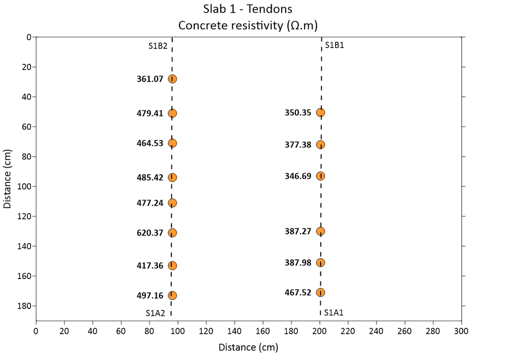
Concurrently, surface electrical resistivity mapping quickly identifies areas of low concrete resistivity and high moisture/chloride permeability, highlighting the surface corridors most susceptible to aggressive ingress.
Phase 2 – IE + UPE: Because corrosion concentrated heavily at structural discontinuities (construction joints and slab-girder interfaces), detailed acoustic testing should focus along these critical zones. IE and UPE serve complementary roles: IE provides deeper acoustic penetration to identify debonding and anomalies across the full slab depth, while UPE pinpoints specific localized voids within metal PT ducts where the concrete-air interface reflects the signal.
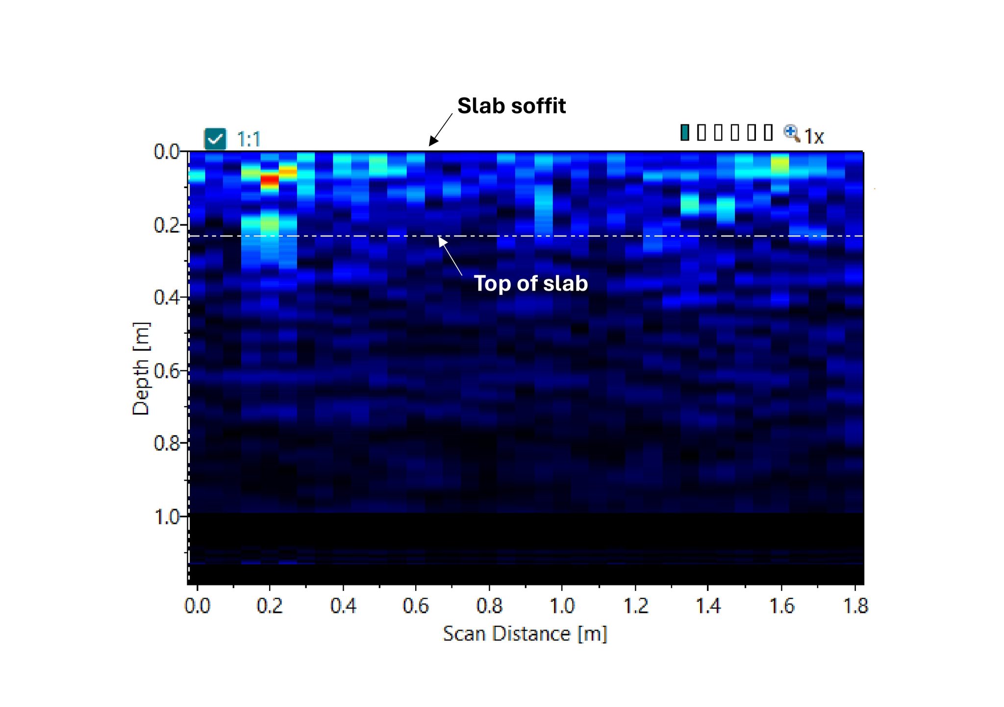
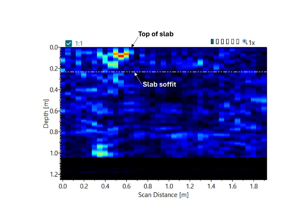
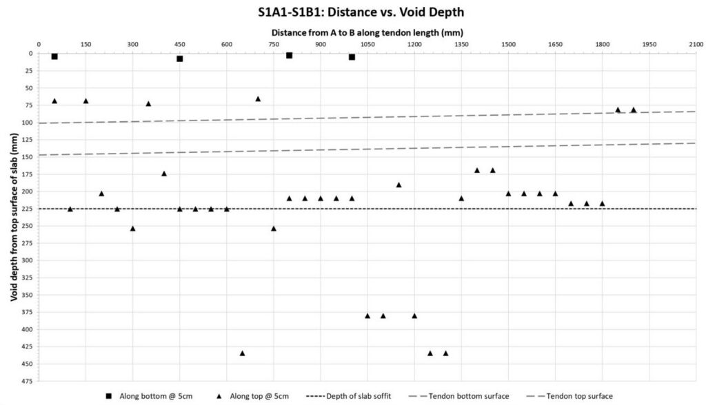
Phase 3 – Half-cell potential + corrosion rate + UPV: Half-cell potential and direct corrosion rate monitoring confirm active corrosion probability and instantaneous rates along the mapped duct lines. UPV measurements correlate directly with internal concrete uniformity and verified corrosion rates, validating areas of active steel degradation.
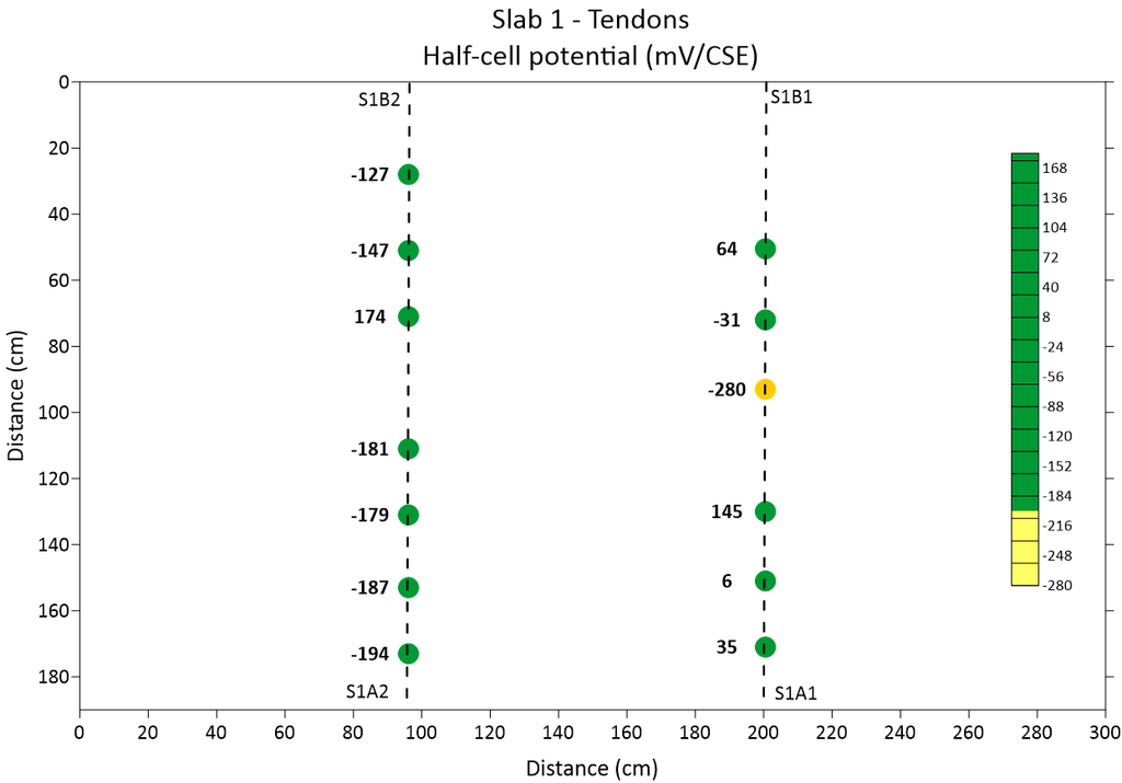
Phase 4 – Targeted intervention: By cross-referencing acoustic void maps with electrochemical corrosion hotspots, asset managers and structural consultants can replace high-risk exploratory coring with targeted inspections. This strategic workflow directly informs repair decisions, prioritizing necessary rehabilitation where internal PT wire section loss is most critical and ultimately extending the service life of aging bridge infrastructure.
Essential Findings & Future Implications for PT Infrastructure
The findings from the Champlain Bridge deck slabs confirm that visual inspections alone cannot detect severe internal tendon corrosion and grout voids embedded within post-tensioned concrete. Because individual diagnostic tools present distinct limitations, reliable condition assessment requires an integrated, multi-technique approach combining electromagnetic, acoustic, and electrochemical non-destructive testing.
Going forward, the bridge management industry must transition from isolated, reactive screening methods to standardized, multi-technique diagnostic frameworks. Adopting and integrating this NDT framework will enable asset managers to prioritize targeted interventions at vulnerable structural interfaces, effectively optimizing rehabilitation strategies and budgets, while extending the service life of aging PT infrastructure.
“Detection of corrosion effects on prestressed concrete bridge deck slabs from the Champlain Bridge through non-destructive testing techniques,” is published in Structural Concrete (Wiley). Read the full article.