Why Ensuring Proper Quality Control is Important
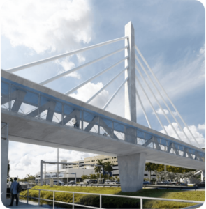
On March 15th, 2018 a 950-ton, partially assembled pedestrian bridge at Florida International University (FIU) collapsed onto the busy highway below after only five days of its placement, killing six people and leaving nine seriously injured. The 14.2-million-dollar bridge encompassed an open truss with a top chord that served as a canopy over the wider bottom walking-surface chord. Pipes that would have the appearance of cables were to be extended downward from a 109-ft-high central pylon. The concrete deck was to have two-way post-tensioning tendons. The concrete truss members, including the canopy, were to have been compressed with high-strength steel cable and bars. A conceptual image of the bridge is shown in Fig. 1.
The bridge was built using the so-called Accelerated Bridge Construction (ABC) method. In this method, prefabricated components are built offsite and then transported and assembled in-place. This method is currently being preferred over conventional bridge construction due to the lower traffic disruption periods and the overall faster construction. Five days before the collapse, self-propelled modular transporters (SPMT) were used to transport the bridge’s 32-ft-wide, 950-ton main span onto permanent supports, in just a few hours.
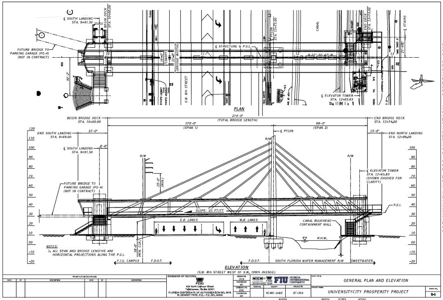
Construction of the pedestrian bridge was behind schedule and millions over budget. This was partially due to a key change in the design and placement of one of its support towers. In October 2016, the Florida Department of Transportation ordered FIU and its contractors to move the central pylon 11 feet north to the edge of a canal, widening the gap between the crossing’s end supports and requiring some new structural design.
Two days before the collapse, according to a New York Times report, small cracks were observed at the slab’s north end, where the failure appears to have occurred. The cracks caused concern that led the engineers to discuss the integrity of the span. However, it was proclaimed safe a few hours before the FIU bridge collapse.
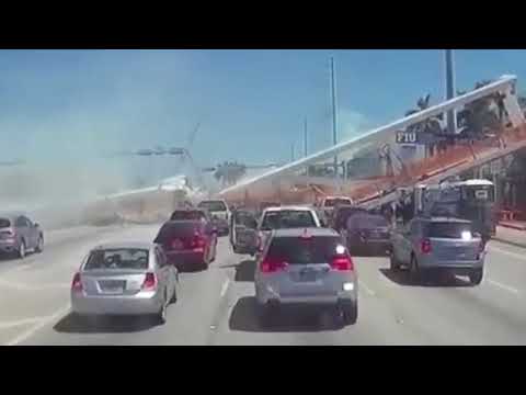
Footage has showed that the structure failed at its north end. National Transportation Safety Board (NTSB) investigators noted that, at the time of the FIU bridge collapse, crews were applying post-tensioning force on one of the diagonal members at the north end of the structure. Local authorities have also stated that workers conducted a stress test the day of the collapse.
Some of the earliest reports pointed fingers to the ABC method. Although ABC has only gained interest recently, it must be noted that it is not fundamentally anything new. Rapid-installation techniques are widely used, with a great deal of success, all around the world. Examples of such projects in the US include the numerous ones mentioned here. For a bridge such as the FIU Pedestrian Bridge, spanning a busy highway, it would be rather surprising not to adopt an ABC approach.
Many of the early commentaries have also noted the obvious difference between the bridge’s temporary condition and the final condition shown in design visualizations. The suggestion is made in such commentaries that the bridge could not be expected to stand up without the diagonal stays in place.
However, according to the proposal by MCM and FIGG, the structure was designed to meet the strength design criteria without the stays. The truss was designed to be strong enough on its own to carry its self-weight plus pedestrian loading. The proposal states that the stays are only there to control vibration and to add a visual effect.
Furthermore, the design live load required in FIU’s specifications is 90 psf (4 kPa), on a span 31-feet (9.4m) wide by 175-feet (53.3m) long; a total live load of roughly 200 tons. The footage also clearly shows that bridge was carrying nowhere near this load at the time of collapse.
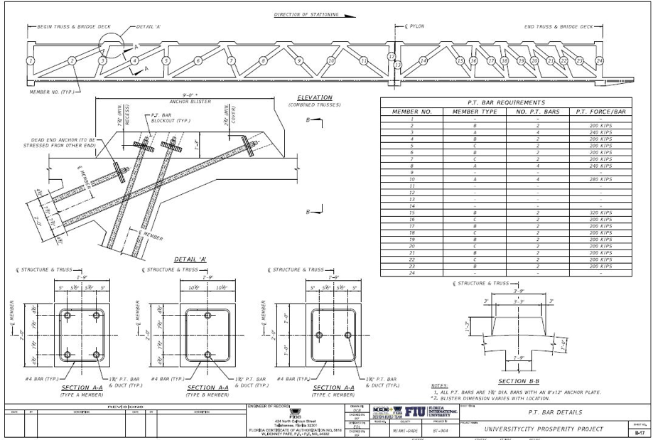
Footage has shown that work was taking place on the bridge directly above one of the truss nodes. A crane can be seen to be in place, and appears to have been supporting equipment, in two videos which show the bridge collapsing. One postulation states that while crews were trying to even out the stresses in the bridge, over-tightening a tension rod may cause it to snap, bringing down the bridge. This is supported by footage from the bridge that shows a tension rod sticking out of the wreckage still attached to the hydraulic cylinder that would have been used to tighten it. However, it is not clear what work was taking place. The preliminary drawings in the proposal shown in Fig. 3 indicate this to be the position of dead-end anchorages for the web prestressing, not stressing anchorages, but it is possible that was changed during detailed design.
The aforementioned discussions on the reasons of the failure can be, at best, regarded as postulations. Further evidence will be available and summarized by several investigation agencies such as NTSB. Such catastrophic failures clearly shed a light at the methods used for quality assurance and quality control used for such critical projects. It is important to ensure that safety measures are respected; such as closing the road traffic surrounding construction during critical, high-risk, project phases. It is, obviously, critical to ensure that proper quality control methods are implemented when using materials and methods during such phases. Some quality assurance methods, such as non-destructive testing methods, are at present viewed as optional requirements for construction projects. These methods can decrease the probability of occurrence of such failures and will be viewed in the future as an essential component of the construction industry. Examples of such quality assurance/control methods include using sensors to monitor real-time concrete properties during these critical construction operations. The use of these sensors will ensure that the mechanical properties of the materials conform to those used for the design and guarantee the integrity of the structure from both a structural as well as a durability point of view.
Header photo courtsey of WCTV