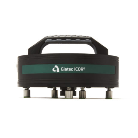
iCOR® 

Wireless NDT Corrosion Detection

A device for evaluating and measuring the rate of rebar corrosion in seconds

iCOR® | Wireless NDT Corrosion Detection

Non-Invasive & Non-Destructive Wireless Technology 

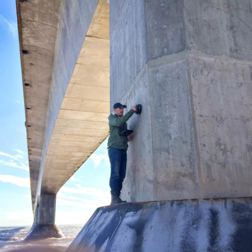
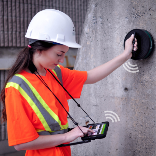
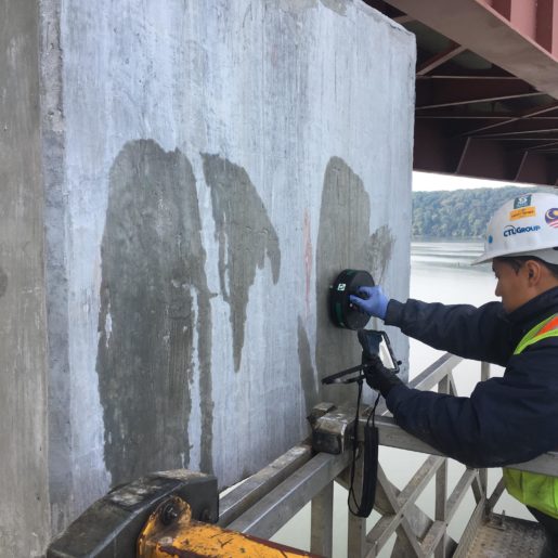
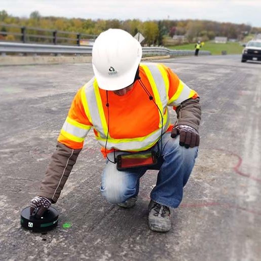
Unlike other devices which must drill into the concrete and physically connect to the rebar to evaluate corrosion, the iCOR® is completely non-destructive.

Surf™ | Concrete Surface Resistivity

Fast & Accurate Real-Time
Data in Seconds 

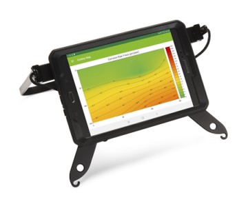
Data is collected, analyzed, and stored wirelessly within the mobile app on the tablet provided where it can be easily shared with team members.

SmartRock® | Concrete Temperature and Strength Maturity Sensor

Automatic Report Generation Simple & Easy-To-Use 

Detailed corrosion evaluation of reinforced concrete structures is presented as contour maps which are accessible in real-time on the tablet.

iCOR® | Wireless NDT Corrosion Detection

Recipient of NACE Corrosion Innovation Award

iCOR is the most advanced wireless corrosion measurement device for evaluating the health of reinforced concrete structures. iCOR detects corrosion potential, corrosion rate, and in-situ electrical resistivity. In 2019, the iCOR was presented the Corrosion Innovation Award by the National Association of Corrosion Engineers (NACE).

Applications​

  • Detection of corrosion in reinforcement
  • Measurement of rebar corrosion rate
  • Evaluation of corrosion potential of rebar
  • Measurement of in-situ electrical resistivity
  • Assessment of concrete durability
  • Rehabilitation and repair of concrete structures
iCOR® | Wireless NDT Corrosion Detection

Software

  • Real-time contour mapping of corrosion rate, electrical resistivity, and corrosion potential
  • Accurate non-subjective algorithm-based interpretations
  • Multiple and directional parameters tested in a single measurement
  • Easy reporting and data exporting

Hardware

  • Non-destructive, and non-invasive wireless technology
  • Measurements obtained and evaluated within seconds
  • Simple and easy-to-use with minimal training required
  • Single-person operation device
  • Tablet included with free Android app
  • Award-winning patented technology
iCOR® | Wireless NDT Corrosion Detection

ASTM C876 – Standard Test Method for Corrosion Potentials of Uncoated Reinforcing Steel in Concrete

Patented Technology

iCOR benefits from the patented CEPRA technology that makes it possible to estimate the rate of rebar corrosion through a noninvasive, non-destructive approach. This means that the need to connect the device to the rebar to obtain measurements, which is the case for other commercial devices, is eliminated with the iCOR.

Testing Time   3 to 30 seconds  
Corrosion Rate Range   0 to 500 μm / year  
Corrosion Potential Range   -800 to +200 mV / CSE  
Electrical Resistivity Range   0 to 10,000 Ω • m 

Additional resources on concrete corrosion:

  1. Alonso, C., Andrade, C., and Gonzalez, J. A. (1988). Relation between Resistivity and Corrosion Rate of Reinforcements in Carbonated Mortar Made with Several Cement Types. Cem. Concr. Res., 18(5), 687-698. 
  2. Andrade, C., and Gonzalez J. A. (1978). Quantitative Measurements of Corrosion Rate of Reinforcing Steels Embedded in Concrete Using Polarization Measurements. Werkst. Korros., 29(8), 515-519. 
  3. Andrade, C., & Alonso, C. (1996). Corrosion rate monitoring in the laboratory and on-site. Construction and Building Materials, 10(5), 315-328. 
  4. Andrade, C., & Alonso, C. (2001). On-site measurements of corrosion rate of reinforcements. Construction and Building Materials, 15(2-3), 141-145. 
  5. Andrade, C., Castelo, V., Alonso, C., & Gonzalez, J. (1984). The Determination of the Corrosion Rate of Steel Embedded in Concrete by the Polarization Resistance and AC Impedance Methods. Corrosion Effect of Stray Currents and the Techniques for Evaluating Corrosion of Rebars in Concrete, 43-63. 
  6. Andrade, C., & González, J. A. (1978). Quantitative measurements of corrosion rate of reinforcing steels embedded in concrete using polarization resistance measurements. Werkstoffe Und Korrosion, 29, 515-519. 
  7. Arup, H. (1983). The Mechanisms of the Protection of Steel by Concrete. Society of Chemical Industry, , 151-157. 
  8. ASTM C876-91(1999). Standard Test Method for Half-Cell Potentials of Uncoated Reinforcing Steel in Concrete. 
  9. ASTM G1-90 (1999). (2002). Standard Practice for Preparing, Cleaning and Evaluating Corrosion Test Specimens. 
  10. Balabanic, G., Bicanic, N., and Durekovic, A. (1995). Numerical Analysis of Corrosion Cell in Concrete. Int. J. Eng. Modell., 8(1-2), 1-5. 
  11. Bastidas, D. M., González, J. A., Feliu, S., Cobo, A., & Miranda, J. M.  (2007). A Quantitative Study of Concrete-Embedded Steel Corrosion Using Potentiostatic Pulses. System, 7, 10. 
  12. Berke, N. S., Shen, D. F., & Sundberg, K. M. (1990). Comparison of Current Interruption and Electrochemical Impedance Techniques in the Determination of Corrosion Rates of Steel in Concrete. The Measurement and Correction of Electrolyte Resistance in Electrochemical Tests. 
  13. Berke, N. S., Shen, D. F., & Sundberg, K. M. (1990). Comparison of the Polarization Resistance Technique to the Macrocell Corrosion Technique. Corrosion Rates of Steel in Concrete, , 38-51. 
  14. Berkeley, K. G. C., and Pathmanaban, S. (1990). Cathodic Protection of Reinforcement Steel in Concrete, Butterworth-Heinemann, London. 
  15. Bertolini, L., Elsener, B., Pedeferri, P., and Polder, R. (2004). Corrosion of Steel in Concrete, WILEY-VCH Verlag GmbH & Co. KGaA, Weinheim, Germany. 
  16. Bohni, H. (2005). Corrosion in Reinforced Concrete Structures, CRC Press, New York. 
  17. Broomfield, J. P. (1997). Corrosion of Steel in Concrete: Understanding, Investigation and Repair Sponpress. 
  18. Browne, R. D., Geoghegan, M. P., & Baker, A. F. (1983). Analysis of Structural Condition from Durability Results. Corrosion of Reinforcement in Concrete Construction.Chichester: Ellis Horwood, , 193-222. 
  19. Cady, P. D., & Gannon, E. J. (1992). Condition Evaluation of Concrete Bridges Relative to Reinforcement Corrosion. Volume 8: Procedure Manual. 
  20. Cleland, D. J., Yeoh, K. M., & Long, A. E. (1997). Corrosion of reinforcement in concrete repair. Construction and Building Materials, 11, 233-238. 
  21. Cox, R. N., Cigna, R., Vennesland, Ø, & Valente, T. (1997). COST 509: Final report Corrosion and protection of metals in contact with concrete. 
  22. Elsener, B. (2001). Half-cell potential mapping to assess repair work on RC structures. Construction and Building Materials, 15(2-3), 133-139. 
  23. Elsener, B. (2002). Macrocell corrosion of steel in concrete–implications for corrosion monitoring. Cement and Concrete Composites, 24(1), 65-72. 
  24. Elsener, B. (2005). Corrosion rate of steel in concrete—Measurements beyond the Tafel law. Corrosion Science, 47(12), 3019-3033. 
  25. Elsener, B., Andrade, C., Gulikers, J., Polder, R., & Raupach, M. (2003). Hall-cell potential measurements—Potential mapping on reinforced concrete structures. Materials and Structures, 36(7), 461-471. 
  26. Elsener, B., & Bohni, H. (1988). Potential Mapping and Corrosion of Steel in Concrete. Corrosion Rates of Steel in Concrete, , 143-156. 
  27. Elsener, B., & Böhni, H. (1995). Condition evaluation of reinforced concrete bridges–The benefits of potential mapping. Proc. 6 thInt. Conf. Structural Faults Repair, London, 47-52. 
  28. Elsener, B., Muller, S., Suter, M., & Bohnl, H. (1990). Corrosion Monitoring of Steel in Concrete–Theory and Practice. Corrosion of Reinforcement in Concrete, , 348-357. 
  29. Elsener, B., Wojtas, H., & Boehni, H. (1994). Galvanostatic Pulse Measurements—Rapid On-Site Corrosion Monitoring. Corrosion and Corrosion Protection of Steel in Concrete, 1, 236-246. 
  30. Feliu, S., Andrade, C., González, J. A., & Alonso, C. (1996). A new method for in-situ measurement of electrical resistivity of reinforced concrete. Materials and Structures, 29(6), 362-365. 
  31. Feliu, S., Gonzalez, J. A., & Andrade, C. (1996). Electrochemical methods for on-site determinations of corrosion rates of rebars. Techniques to Assess the Corrosion Activity of Steel Reinforced Concrete Structures, 
  32. Feliu,S., Gonzalez, J.A., Escudero, M. L., & Andrade, M. C. (1990). Possibilities of the guard ring for electrical signal confinement in the polarization measurements on reinforcements. Corrosion (Houston, TX.), 46(12), 1015-1020. 
  33. Feliu, S., Gonzalez, J. A., feliu Jr., S., & Andrade, M. C. (1990). Confinement of the Electrical Signal for in Situ Measurement of Polarization Resistance in Reinforced Concrete. ACI Materials Journal, 87(5). 
  34. Flis, J., Sabol, S., Pickering, H. W., Sehgal, A., Osseo-Asare, K., & Cady, P. D. (1993). Electrochemical measurements on concrete bridges for evaluation of reinforcement corrosion rates. Corrosion-Houston TX, 49, 601-601. 
  35. Garcés, P., Andrade, M. C., Saez, A., & Alonso, M. C. (2005). Corrosion of reinforcing steel in neutral and acid solutions simulating the electrolytic environments in the micropores of concrete in the propagation period. Corrosion Science, 47(2), 289-306. 
  36. Ge, J., and Isgor, O. B. (2006). On the Numerical Solution of Laplace’s Equation with Nonlinear Boundary Conditions for Corrosion of Steel in Concrete. ISCCBE Conference (CD-Rom), Montreal, Canada. 
  37. Ge, J., and Isgor, O. B. (2007). Effects of Tafel slope, exchange current density and electrode potential on the corrosion of steel in concrete. Materials and Corrosion(1995), 58(8), 573-582. 
  38. Geenen, F. M. (1991). Characterization of Organic Coatings With Impedance Measurements. Doctoral Dissertation, Delft University of Technology, 
  39. Ghods, P., Isgor, O. B., and Pour-Ghaz, M. (2007). A Practical Method for Calculating the Corrosion Rate of Uniformly Depassivated Reinforcing Bars in Concrete. Mater. Corros., 58(4), 265-272. 
  40. Ghods, P., Isgor, O. B., & McRae, G. (2009)The Effect of Concrete Pore Solution Composition on the Quality of Oxide Films on Black Steel Reinforcement. Cement and Concrete Composites, 31(1), 2-11. 
  41. GjØrv, O. E., Vennesland, Ø., and El-Busiady, A. H. S. (1977). Electrical Resistivity of Concrete in the Oceans. Proc., 9th Annual Offshore Technology Conference, Houston, Texas, 581-588. 
  42. González, J. A., Cobo, A., González, M. N., & Feliu, S. (2001). On-site determination of corrosion rate in reinforced concrete structures by use of galvanostatic pulses. Corrosion Science, 43(4), 611-625. 
  43. Gowers, K. R., & Millard, S. G. (1999). Measurement of Concrete Resistivity for Assessment of Corrosion Severity of Steel Using Wenner Technique. ACI Materials Journal, 96(5) 
  44. Gowers, K. R., Millard, S. G., Gill, J. S. and Gill, R. P. (1994). programmable Linear Polarization Meter for Determination of Corrosion Rate of Reinforcement in Concrete Structures. Br. Corros. J., 29(1), 25-32. 
  45. Gu, P., & Beaudoin, J. J. (1998). Obtaining Effective Half-Cell Potential Measurements in Reinforced Concrete Structures. Institute for Research in Construction: Construction Technology Update, 18(4) 
  46. Gulikers, J. (2005). Theoretical Considerations on the Supposed Linear Relationship between Concrete Resistivity and Corrosion Rate of Steel Reinforcement. Mater. Corros., 56(6), 393-403. 
  47. Isgor, O. B., and Razaqpur, A. G. (2004). Finite Element Modeling of Coupled Heat Transfer, Moisture Transport and Carbonation Processes in Concrete Structures. Cem. Concr. Compos., 26(1), 57-73. 
  48. Jackson, P. D. (1981). Focussed electrical resistivity arrays: some theoretical and practical experiments. Geophysical Prospecting, 29(4), 601-626. 
  49. John, D. G. (1981). Use of AC impedance technique in studies on steel in concrete in immersed conditions. British Corrosion Journal, 16(2) 
  50. Jones, D. A. (1996). Principles and Prevention of Corrosion (ed.). 
  51. Kranc, S. C., & Sagüés, A. A. (1993). Computation of Reinforcing Steel Corrosion Distribution in Concrete Marine Bridge Substructures. Corrosion National Association of Corrosion Engineers Annual Conference. 
  52. Kranc, S. C., and Sagues, A. A. (1994). Computation of Reinforcing Steel Corrosion Distribution in Concrete Marine Bridge Substructures. Corrosion, 50(1), 50-61. 
  53. Langford, P., & Broomfield, J. P. (1987). Monitoring the corrosion of reinforcing steel. Construction Repair, 1(2), 32-36. 
  54. Law, D. W., Millard, S. G., & Bungey, J. H. (2000). Linear polarisation resistance measurements using a potentiostatically controlled guard ring. NDT & E International, 33(1), 15-21. 
  55. Li, D., Flis, J., Sehgal, A., Kho, Y. T., & Saboi, S. (1992). Condition Evaluation of Concrete Bridges Relative to Reinforcement Corrosion. Volume 2. Method for Measuring the Corrosion Rate of Reinforcing Steel. 
  56. Luping, T. (2002). Calibration of the Electrochemical Methods for the Corrosion Rate Measurement of Steel in Concrete NORDTEST Project No. 1531-01. SP RAPPORT-STATENS PROVNINGSANSTAL. 
  57. Martinez, I., Andrade, C., Rebolledo, N., Bouteiller, V., Marie-Victoire, E., & Olivier, G. (2008). Corrosion Characterization of Reinforced Concrete Slabs with Different Devices. Corrosion-Houston TX, 64(2), 107. 
  58. Matsuoka, K., Kihira, H., Ito, S., & Murata, T. (1988). Corrosion Monitoring for Reinforcing Bars in Concrete. Corrosion Rates of Steel in Concrete, , 103-117. 
  59. Millard, S. G., & Gowers, K. R. (1992). Resistivity assessment of in-situ concrete: the influence of conductive and resistive surface layers. Structures and Buildings, 94(4), 389-396. 
  60. Millard, S. G., Law, D., Bungey, J. H., & Cairns, J. (2001). Environmental influences on linear polarisation corrosion rate measurement in reinforced concrete. NDT & E International, 34(6), 409-417. 
  61. Morris, W., Moreno, E. I., & Sagues, A. A. (1996). Practical evaluation of resistivity of concrete in test cylinders using a Wenner array probe. Cement and Concrete Research, 26(12), 1779-1787. 
  62. Munn, R. S., and Devereux, O. F. (1991). Numerical Modeling and Solution of Galvanic Corrosion Systems. Part I. Governing Differential Equation and Electrodic Boundary Conditions. Corrosion, 47(8), 612-618. 
  63. Newman, J. (1966). Resistance for Flow of Current to a Disk. Journal of the Electrochemical Society, 113, 501. 
  64. Newton, C. J., & Sykes, j. M. (1988). A galvanostatic pulse technique for investigation of steel corrosion in concrete. Corrosion Science, 28(11), 1051-1074. 
  65. Oelssner, W., Berthold, F., & Guth, U. (2006). The iR drop-: well-known but often underestimated in electrochemical polarization measurements and corrosion testing. Materials and Corrosion (1995), 57(6), 455-466. 
  66. Polder, R. B. (2001). Test methods for on site measurement of resistivity of concrete—a RILEM TC-154 technical recommendation. Construction and Building Materials, 15(2-3), 125-131. 
  67. Pruckner, F., & Gjrv, O. E. (2002). Patch repair and macrocell activity in concrete structures. ACI Materials Journal, 99, 143-148. 
  68. Ramniceanu, A. (2004). Correlation of Corrosion Measurements and Bridge Conditions with NBIS Deck Rating. M.Sc. Thesis, 
  69. Redaelli, E., Bertolini, L., Peelen, W., and Polder, R. (2006). FEM-models for the Propagation Period of Chloride Induced Reinforcement Corrosion. Mater Corros., 57(8), 628-635. 
  70. Revie, R. W., & Uhlig, H. H. (2008). Corrosion and Corrosion Control Wiley-Interscience. 
  71. RILEM TC 154-EMC. (2003). Half-cell Potential Measurements – Potential Mapping on Reinforced Concrete Structures. Mater. Struct., 36(7), 461-471. 
  72. Sagues, A. A., and Kranc, S. C. (1992). On the Determination of Polarization Diagrams of Reinforcing Steel in Concrete. Corrosion, 48(8), 624-633. 
  73. Sehgal, A., Kho, Y. T., Osseo-Asare, K., & Pickering, H. W. (1992). Comparison of corrosion rate-measuring devices for determining corrosion rate of steel-in-concrete systems. Corrosion- Houston TX, 48, 871-871. 
  74. Sehgal, A., Li, D., Kho, Y. T., Osseo-Asare, K., & Pickering, H. W. (1992). Reproducibility of Polarization Resistance Measurements in Steel-in-Concrete Systems. Corrosion- Houston TX, 48, 706-706. 
  75. Stern, M., & Geary, A. L. (1957). Electrochemical Polarization, LA theoretical analysis of the shape of polarization curves. Journal of the Electrochemical Society, 104, 56-63. 
  76. Stratfull, R. (1957). The corrosion of steel in a reinforced concrete bridge. Corrosion, 13(3), 173-179. 
  77. Uhlig, H. H., and Revie, R. W. (1985). Corrosion and Corrosion Control, 3rd Ed., John Wiley & Sons, New York. 
  78. Videm, K., & Myrdal, R. (1997). Electrochemical Behavior of Steel in Concrete and Evaluation of the Corrosion Rate. Corrosion- Houston TX, 53, 734-742. 
  79. Virmani, P. (2002). Corrosion Costs and Preventive Strategies in the United States. Publication no.FHWA-RD-01-156 (Washington, DC: FWHA, 2002), 
  80. Warkus, J., Brem, M., and Raupach, M. (2006). BEM-models for the Propagation Period of Chloride Induced Reinforcement Corrosion. Mater. Corros., 57(8), 636-641. 
  81. Zhang, J., & Mailvaganam, N. P. (2006). Corrosion characteristics and key electrochemical factors in patch repair. Canadian Journal of Civil Engineering, 33(6), 785-793. 
Part No.ItemDescription
900081iCOR Beta unit, Tablet with hands-free carrying support, Data Analysis App., User manual, Connection sponges, USB cable, Conductive solution, Carrying Case.

FAQs

There is no standard available yet for the corrosion rate measurement based on the patented CEPRA technique. Giatec iCOR is the only product on the market that does not require the connection to the reinforcement to obtain corrosion rate. In addition to corrosion rate and resistivity, the iCOR also provides a standard half-cell measurement unit for corrosion potential measurement; the half-cell measurement is optional as it requires connection to the reinforcement. The standard for corrosion potential measurement of rebar in concrete is ASTM C876. 

The user needs to input the cover thickness in the software for corrosion rate measurement. The range of cover thickness can vary from 0.4 to 3.5 in (1 cm to 9 cm) with an increment of 0.4 in (1 cm). 

iCOR measurements are sensitive to the concrete moisture. The dryer the concrete is, the higher the electrical resistivity values, the lower the corrosion rate and more positive the corrosion potential will be. Pre-wetting the concrete surface is required before the use of any corrosion measurement. In the case of iCOR, a wet connection between the electrodes and surface of concrete through sponges is required to obtain reliable measurements. 

The iCOR uses a solid-base Ag/AgCl electrode for the half-cell measurement. This is a maintenance- free electrode capable of doing upside down measurement and less prone to contamination due to chlorides. Ag/AgCl has a fixed potential offset compared to the Cu/CuSO4 electrode; the iCOR software accounts for this difference and presents the results in mV/CSE (i.e. Cu/CuSO4 Electrode) as per the ASTM C876. 

The iCOR applies an electrical current between the two outer electrodes; any non-conductive layer will cause interruption in the flow of current into concrete. If the epoxy on the bar is perfectly intact, no measurement would be possible. 

What is the battery life of the device?

The iCOR battery will last a full day of use, simply make sure it is fully charged the night before. The unit roughly takes 4 hours to charge. The tablet will indicate the level of battery life on the unit at all times.  We also recommend having the tablet charged the night before, the tablet will have the limiting battery life in the package (similar to a phone). In addition, it is possible to utilize an external battery pack that can be used to mitigate the battery consumption of the tablet.

What are the limitations of the device?

In general, any feature in the reinforced concrete structure that breaks electrical continuity at the point of measurement will not permit testing, i.e. epoxy coated/galvanized rebar, tensioning ducts sheathing (plastic), asphalt wearing surfaces/waterproofing, fiber reinforced concrete. This is not a limitation of the iCOR but applies to all corrosion detection devices.

Some other aspects of the analyzed structure might affect the readings, such as the presence of voids/ large cracks. As a rule, any nonconductive layer or air layer will block the current from reaching the reinforcement. Another limitation that you may encounter in your region is the temperature measurement range. There is no corrosion activity in the sub 0°C (32°F) temperature as the water inside the concrete becomes ice, it drastically changes the concrete resistivity behavior which would impact the results. Those are not limitations of our equipment but limitations of corrosion rate measurement in general.

What is the minimum and maximum cover depth for inspection?

A minimum of 10 mm is recommended as the minimum cover depth for inspection. 90 mm is the maximum rebar cover allowable for the iCOR to perform an accurate measurement. Moreover, the equipment will always read the first rebar layer, so if the intent is to read the rebars that are on other layers, the current will be drawn toward the first rebar layer only. When using the corrosion potential, the greater the cover depth, the lower that reading signal gets. Using the half-cell potential on cover depths >90 mm, the interpretation of the results must be carefully made as small differences can represent local corrosion.

Should corrosion rate measurements be performed if the rebar has corroded severely and the diameter has decreased drastically?

In that situation, the concrete itself would demonstrate significant signs of corrosion. If the corrosion process is severe enough to reduce drastically the rebar diameter, its expansion will deteriorate the concrete, and mapped cracks and delamination will appear on the concrete surface. The primary goal of the equipment is to identify corroding rebars that did not yet severely damage the concrete and take actions to prevent further deterioration.

Are there any recommendations to perform corrosion rate and corrosion potential measurements at the same time?

If it is decided to make a 3 in 1 measurement with the iCOR, when pressing the measurement button, first a half-cell measurement will be taken, followed by both the electrical resistivity and corrosion rate simultaneously. The corrosion rate and electrical resistivity measurement will polarize the reinforcement therefore the half-cell measurement needs to be performed first at a specific location. The iCOR only polarizes the rebar for a short period of time, when the measurements are set to 3, 6 or 10 seconds, however it is always recommended to wait at least 30 minutes before repeating a measurement at the exact same location.

How should the surface of the concrete be prepared before a corrosion rate measurement?

It is highly recommended to pre-wet the surface of the concrete before the measurement is taken as described in ASTM C876. The ideal condition to perform a test is in a saturated surface dry (SSD) condition. This is, however, sometimes hard to achieve on site. Ponding the surface before the test is a very good preparation step. If ponding is used, make sure the excess water on the surface dries or gets removed before the test as excess running water between the surface of the concrete and the iCOR electrodes will cause errors in the measurements.

What is the minimal spacing between the rebars?

There is a limitation to the spacing of the rebar, which is related to the two voltage response electrodes located at the center of the device. If there are two sections of rebar passing through these electrodes, the results will not output correctly. So, the limitation spacing is around 10 cm or 4 in.

For rebars near the edge of the concrete element, are there any limitations?

As long as the 4 electrodes in the measurement direction make contact with the concrete surface on top of the reinforcement, it will be possible to perform a measurement. For example, in the y-direction (handle direction) the current is passed through the outer two electrodes, and the voltage response is measured by the inner electrodes. This statement also applies to the curve surfaces (e.g : columns).

What is the benefit of taking half-cell and corrosion rate measurements together?

With the iCOR, it is possible to perform different types of measurements together or independently (refer to user manual for more information). The five types of measurements are:

1 – Corrosion rate (includes concrete resistivity)

2 – Corrosion rate (includes concrete resistivity) and half-cell potential

3 – Half-cell potential

4 – Concrete resistivity

5 – Half Cell potential and concrete resistivity

Half-cell is included in the unit because it is the only standardized corrosion method. It provides a qualitative measurement while the corrosion rate provides a quantitative assessment. The user tends to use both measurements in the earlier test and move away from half-cell because the results obtained from corrosion rate can be correlated. The iCOR is capable of measuring corrosion rate and concrete resistivity without a connection to the reinforcement, but requires one for the half-cell test.

Is it necessary to use a cover meter/rebar locator to identify the rebar location?

Yes, it is necessary to use a rebar detector/ cover meter to localize the rebars before the test. The iCOR must be aligned with the reinforcement. Location of the rebar, cover depth, and size of the reinforcement are all mandatory information that need to be inputted in the iCOR software.

Does the iCOR require a connection to the reinforcement during the test?

Only when the device is used to measure corrosion potential (HCP). If the device is used for corrosion rate and/or electrical resistivity assessment only, the connection to the reinforcement is not necessary. 

Does the half-cell electrode need to be calibrated?

A verification probe is available upon purchasing any iCOR package. It is recommended to verify the device using the reference electrode before conducting corrosion potential mapping. The half-cell doesn’t require calibration, but must be maintained in good condition in order to pass the verification. 

Can the device develop corrosion mapping for non-flat surfaces?

Yes, corrosion maps can be developed for a non-flat surface, the tablet application creates a grid which represents plan surface. In the case of non-flat testing surfaces, for example a column, the measurements taken on the circumference are represented as a surface. The user creates a grid with desired dimension and spacing and measurements can be taken at any location within that grid.

However, in the presence of a non-plan surface, it is important to ensure that all the four electrodes in the measurement direction selected for electrical resistivity and corrosion rate be in contact with the concrete surface.

How to wet the surface?

The best condition is saturated surface dry (SSD). This condition can be achieved by wetting the surface with a water spray,  water hose, sprinkler, pounding the surface, etc.  Wet the surface as much as possible and let it dry for 15-20 minutes before the measurement is taken, making sure there is no running water on the surface of the concrete.

Bring confidence to your mass concreting projects.

A SmartRock®Long Range remote monitoring solution for all your mass concreting.

Giatec® is sponsoring your 1st
SmartRock® Pilot project

Now’s your chance to start building smarter. Get started today to see if you qualify.

Get Real-Time Data with SmartRock®

See how it works today

We use cookies to provide you with a better experience, analyze site traffic and assist in our marketing efforts. By continuing to use this website, you consent to the use of cookies in accordance with our Privacy Policy Page.