

Corrosion is a natural process that occurs when a structure is exposed to elements like CO2 or chloride, which can penetrate the concrete all the way to the steel reinforcement. This can have serious durability and safety consequences, which is why it is important to monitor corrosion using an accurate and trusted method. The half-cell potential test is the only corrosion monitoring technique standardized in ASTM C876 – 15: Standard Test Method for Corrosion Potentials of Uncoated Reinforcing Steel in Concrete. It is used to determine the probability of corrosion within the rebar in reinforced concrete structures. This blog dives into the specifics of concrete corrosion, the half-cell potential measurement for testing concrete corrosion, and the ways in which the data from a half-cell potential device can be interpreted.

The Basics of Concrete Corrosion
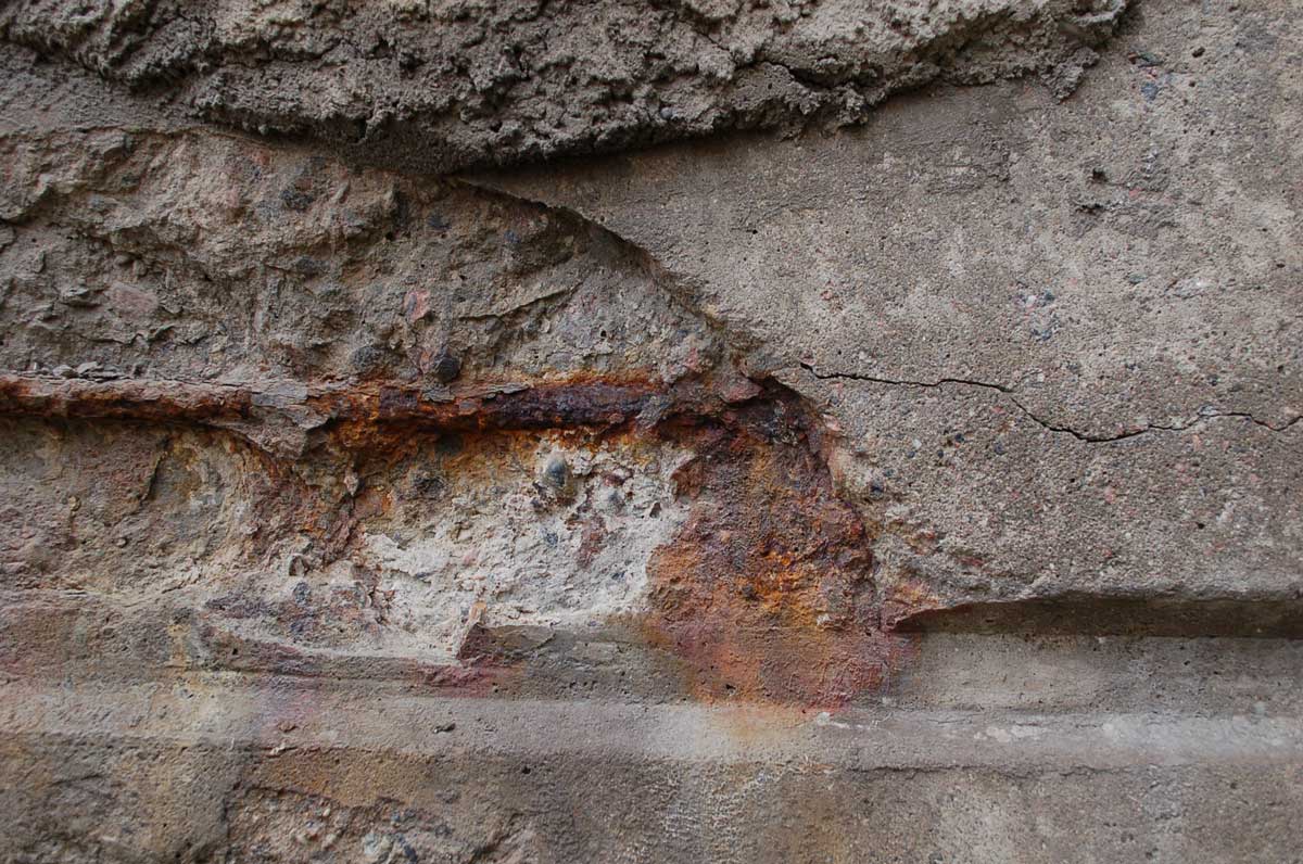
In reinforced concrete structures, there is a natural protective film that forms on the surface and prevents the bar from corroding. With time, chlorides (from de-icing salts or marine exposure) and/or CO2 penetrate the concrete and breakdown that protective layer. Chlorides destabilize the passive film leading to its localized breakdown, while CO2 lowers the pH of the concrete below the level of stability of the passive film. In the presence of oxygen and water, an electrochemical reaction initiates the process of corrosion.
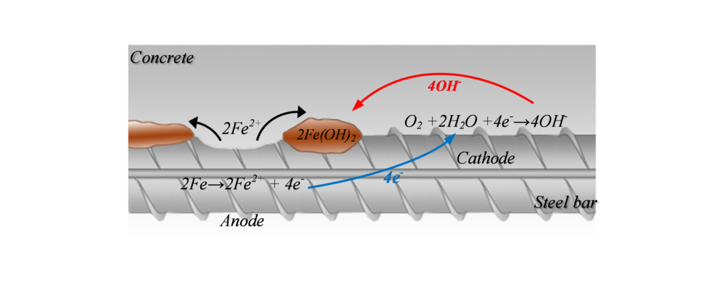
Corrosion can be illustrated as shown in Figure 1, where the metal (rebar) reacts in the solution (available in the concrete pores) and gives away electrons from the anode (where oxidization occurs) to the cathode (where reduction occurs). The positive ions formed at the surface of the anode will react and create corrosion by-products. This electrochemical reaction creates a potential difference, and consequently a corrosion current, between the anodic and cathodic areas at the surface of the steel reinforcement. This current, or the potential distribution on the reinforcement surface, is of interest for half-cell potential measurement.
Half-Cell Potential Measurement
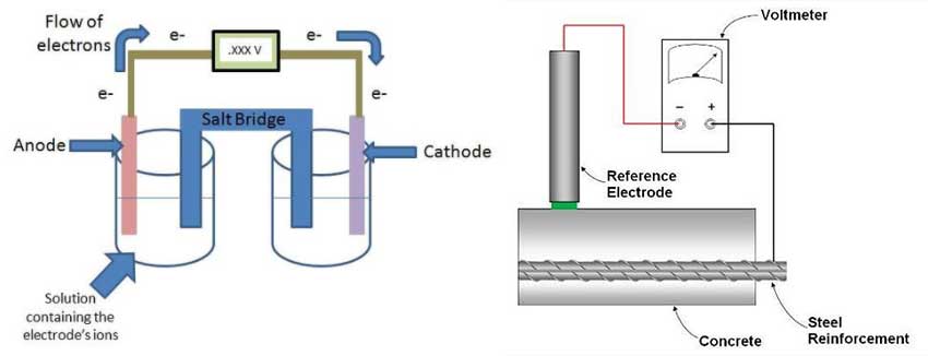
The schematic in Figure 2a represents a cell where each side is referred to as a half-cell. Each half-cell is represented by an electrode in a solution (electrolyte) and both half-cells are connected together. Since one of the electrodes has a higher tendency to corrode compared to the other, that electrode (anode) will oxidize and in turn will donate electrons.
To keep the system in equilibrium and balance the charges in the electrolytes, there will be an exchange of ions through the salt bridge. The voltmeter will measure the potential difference (voltage) between both electrodes, which indicates the rate of dissolution of the anode.
Interested in detecting corrosion in reinforced concrete? Learn more here!
To apply this concept to concrete and to interpret the results of corrosion potential, a reference electrode with a known potential is needed. Typically, for reinforced concrete applications, a copper/copper sulfate electrode (Cu/CuSO4) or silver/silver chloride electrode (Ag/AgCl) is used for the half-cell reference. This reference electrode is connected to the other half-cell represented by the embedded rebar (Figure 2b). By connecting that reference electrode to the reinforcing steel and placing the reference electrode on the surface of the concrete, it is possible to measure the potential difference between the two half-cells.
ASTM C876 provides a guideline on how this measurement can be undertaken, and the relationship between the measured potential values and the corrosion probability. Interpretation of the result is qualitative and is based on the copper sulfate electrode (CSE). Table 1 shows the general interpretation guideline proposed by ASTM, where the measured potential ranges are categorized in three categories; more than 90% chance, less than 10% chance or an uncertain chance of corrosion.
Table 1: Relationship between the potential values and corrosion probability
(adapted from ASTM C876)
| Measured Potential(mV CSE) | Probability of steelcorrosion activity |
|---|---|
>-200 | Less than 10% |
-200 to -350 | Uncertain |
<-350 | More than 90% |
Interpreting Half-Cell Potential Data
At first glance, this test method seems very simple and comprises of the following steps:
- Identify rebar location
- Make a connection with the reinforcement (more than one connection can be required if there is a discontinuity between reinforcements)
- Prepare concrete surface through wetting
Measurements are quick as potential values only take a few seconds to stabilize before the next measurement can be taken. However, there are important limitations in terms of data interpretation that need to be taken into consideration.
The effect of the concrete condition (dry or wet), presence of chloride, absence of oxygen at the rebar surface (due to saturation), cover thickness, concrete resistivity, and temperature are all factors that can influence the results by shifting their potential reading towards a more positive or negative value as shown in Table 2. This can make the data interpretation challenging when using the guidelines given in the ASTM C876 (Table 1), especially around the uncertain measurement ranges.
Table 2: Typical ranges of half-cell potentials of rebar in concrete (adapted from RILEM TC-154, 2003)
| Conditions | Potential values (mV/CSE*) |
|---|---|
| Humid, chloride free concrete | -200 to +100 |
| Wet, chloride contaminated concrete | -600 to -400 |
| Water saturated concrete without oxygen | -1000 to -900 |
| Humid, carbonated concrete | -400 to +100 |
| Dry, carbonated concrete | 0 to +200 |
| Dry concrete | 0 to +200 |
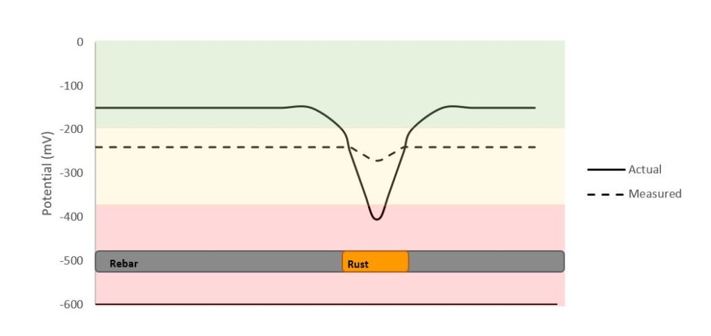
In addition, half-cell measurement is considered to be a zonal measurement as it will take an average potential measurement of the surroundings. An example is illustrated in Figure 3, where the measured potential will show sort of an average over a certain distance and where the actual location of the corroded bar can be challenging to distinguish, even with corrosion potential mapping.
Nevertheless, this technique is being widely used since it is the only corrosion monitoring technique standardized by ASTM. Giatec’s XCell™ device uses a silver/silver chloride electrode, making this NDT device more stable and accurate than those half-cell devices which use a copper/copper sulfate electrode. It can be very useful in doing a quick assessment and identifying the regions where there might be a relatively higher corrosion activity. It remains that the corrosion potential technique’s output is qualitative as it provides information only on the chance of corrosion activity, not quantitative information such as the rate at which the rebar is corroding; this is more useful information when it comes to determining the plan of action for repair or corrosion mitigation.
Related Readings: Obtaining Effective Half-Cell Potential Measurements in Reinforced Concrete Structures
Half-Cell Potential Measurements – Potential Mapping on Reinforced Concrete Structures
**Editor’s Note: This post was originally published in May 2018 and has been updated for accuracy and comprehensiveness in June 2023.


17 Responses
What is the concentration of copper sulphate solution.?
Hello, thank you for your question and interest. The iCOR® device uses the Ag/AgCl electrode as a reference electrode. Our software, based on a fixed electrochemical potential difference between the Ag/AgCl electrode and the Cu/CuSO4 electrode, accounts for this difference and presents the results in mV/CSE (i.e., Cu/CuSO4 Electrode, CSE) as per ASTM C876.
Hi Alicia
I have a similar question as Raghu (May 23, 2020). I have laboratory beams exposed to chloride induced corrosion by utilizing cyclic wetting and drying cycles with a 5% sodium chloride solution. Before testing commend the potential readings were -120 mV on average. The first reading taken after the first cyclic wetting and drying cycle was -400 mV on average. Readings taken after each cycle the increased the potentials, and after 9 cycles the potentials were about -200 mV on average.
Is there any chance you can provide me with some literature that explains the reason for the decreases during early ages, as you explained it to Raghu?
Regarding the -400 mV reading, this could be due to the change in moisture in concrete after cyclic wetting and drying, both moisture, and cyclic wetting and drying will affect the potential of corrosion in the concrete. Please refer to these articles for more information on the results:
o Accelerating effect of wetting-drying cycles on steel bar corrosion in concrete.
o Half-cell potential measurements – Potential mapping on reinforced concrete structures.
o Obtaining effective half-cell potential measurement in the reinforced concrete structure.
HCP with respect to AG/Agcl may be provided like cu electrode.
Hi there, usually, either a copper/copper sulfate electrode (Cu/CuSO4) or a silver/silver chloride electrode (Ag/AgCl) are used as half-cell reference in the case of concrete reinforcement. However, Giatec’s XCell device uses the latter (Ag/AgCl) to increase stability and accuracy in the measurements.
Hi
Can we use two reference electrodes (half cells) on the surface and measure the potential difference? If not why?
With this specific instrumentation, there can only be one reference electrode on the surface of the concrete. The half-cell potential test measures the potential difference in the rebar, which is caused by the corrosion of that rebar. By not connecting the voltmeter to the steel reinforcement, there is no way to measure the electrochemical reaction as the rebar (where the corrosion occurs) is not one of the half-cell.
There is also a non-standardized methods which, instead of giving potential values, will give differential value with a point in the structure where corrosion is unknown. However, the XCell would not be appropriate for this uncommon method, and going with a standardize method is more recommendable.
If you do not have access to the steel reinforcement, look into a non-destructive test method, like the iCOR, which will easily map the corrosion of rebar: https://www.giatecscientific.com/education/how-to-assess-corrosion-in-concrete-with-an-ndt-method/
What is the delta effect in the half-cell potential measurements for detecting reinforcement corrosion
Hi Priyesh, could you elaborate on your question please.
The potential values on concrete in which chlorides are added during concrete preparation, shown more negative(-600) initially and tend towards positive direction like+20 to +10. What it means and please let me know the reason. ..
Hi Raghu, thank you for your comment. Regarding the negative values obtained (i.e. -600mV), in the case where chlorides ions are added in the concrete due to the use of calcium chloride as an accelerator for example, half-cell potential (HCP) values will usually be around -400mV to more negative values. Such readings can be seen at very early age of reinforced concrete when the passive layer may not be formed yet within the matrix. As the concrete starts to harden and free water evaporates from the system and the concrete dries, HCP values tend to shift to higher readings (positive range). Furthermore, it is also good to note that HCP values increase to be less negative due to increasing resistance of carbonated concrete (i.e. presence of carbonation on the concrete surface). Please feel free to reach out to support@giatec.ca for further discussion in details.
Just want to say thanks !
You have explained in a very easy way.
Hi
I am interested in conducting half cell potential test on a concrete wall which is 10 m wide and 14 m high.
How many half cell test shall be conducted on the wall to understand corrosion situation in the entire wall.
Is it that I have to test the full surface area of the wall or test at discrete location are enough?
Thanks
Thank you for your comment Damodar. There is no predefined maximum or minimum spacing between measurements but ASTM C876 Section 7 notes that a spacing of 4ft (1.2m) is usually satisfactory for a quick assessment of the structure. The larger the spacing the more chances of missing localized corrosion. Based on the results you obtain at different locations it would be up to the engineer to decide if more measurement points are required. Please contact support@giatecscientific.com with any other questions.
Excellent, i wood like to know what´s the price?
Hi Victor, thank you for your comment. One of our sales representatives will be in contact with you shortly